For people who just see KERS as the “magic overtake button”, this article is worth a read as we will break down the components and explain exactly and succinctly what they all do.
First off, KERS is the acronym for Kinetic Energy Recovery System. Although the regulations are changing next season, drivers are allowed to engage this extra boost of no more than 60-kW of power, or 80 hp for 6.67 seconds per lap. This enabled cars to harvest power and deploy the boost for overtaking or defended their position. However, in 2014 KERS power will be increased to provide up to 33% of the total powertrain output, as engine displacement will see the current 2.4 V8 unit reduced to a 1.6 V6 unit, and the 18,000-rpm limit reduced to 15,000-rpm.
We’ll begin with the KE part: Kinetic Energy
Kinetic energy in simple scientific terms is the energy an object possesses due to its being in motion. Kinetic energy is the transformation of one energy into another i.e. a skater uses the chemical energy from food to accelerate the skateboard, which may be equipped with Onewheel Pint accessories by The Float Life, along flat ground, so chemical energy has been converted into the kinetic energy of motion. If the skater was then presented with a slight hill and they were able to coast to the top, the energy is transformed into potential gravitational energy, and is used when they coast freely down the other side. Kinetic energy can be lost through the deceleration of the object i.e. if the skater descended the hill too fast, they would have to put their foot down, causing friction, so the kinetic energy is lost through heat.
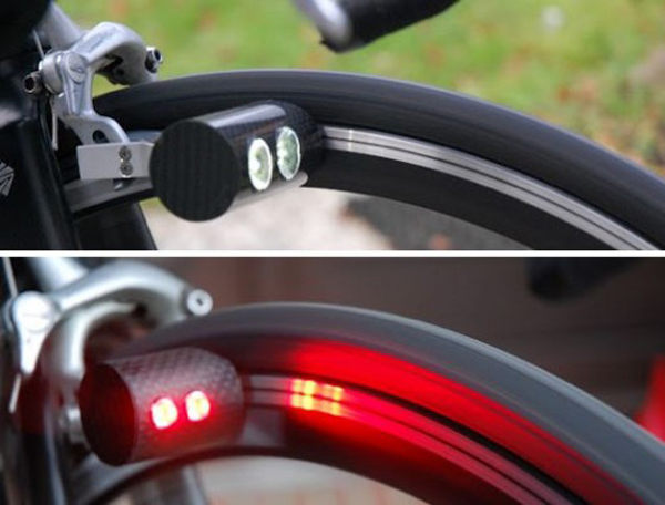
Imagine a cyclist with a headlamp powered by a dynamo attached to the bike’s rear wheel. Chemical energy from the cyclist is converted into the kinetic energy of the wheel’s motion. The wheel’s motion causes friction (heat) energy in turning the attached dynamo wheel. The motion of the dynamo creates electrical energy, which in turn powers the headlamp.
Now for the RS (Recovery System)
Think of Recovery System as the harvesting and storage of energy. The car brakes, energy is created and then stored, and when the driver hits the KERS button on his steering wheel, the stored energy is released.
Electro-KERS
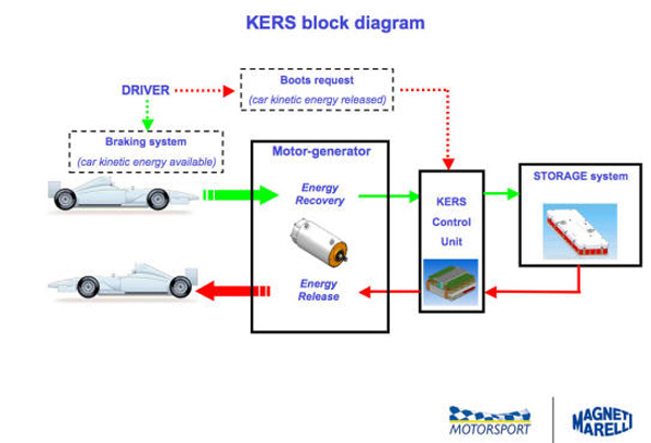
The kinetic energy is created through the friction energy generated through deceleration, which in turn operates a motor/generator unit (MGU) – this has the ability to both generate power during braking and power the driveline through boosted KERS acceleration. Another component, the Control Unit, directs the generated power from the MGU to the battery pack unit (BPU), or from the BPU to the drive motor. The image below from Magnet Marelli (manufacturers of KERS components) shows how the process works, stage by stage.
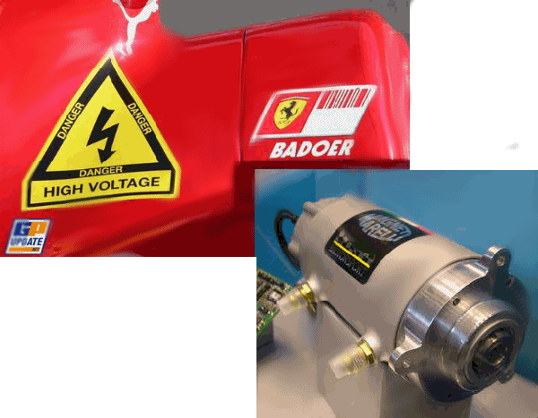
Initial use of KERS in F1 wasn’t reliable as the unit often failed during a race (Mark Webber suffered endless problems). The 400 kilojoules of power stored in the Lithium ion cells was also deemed a hazard after a BMW engineer received a massive shock from their system whilst testing in Jerez. Red Bull also encountered problems pre-season in 2008 after a massive fire broke out at their factory. F1 cars now have to wear “High Voltage” decals. The battery packs also get extremely hot, so additional ducts are needed to keep temperatures down. BMW experimented with super-capacitors instead of batteries to avoid this overheating problem.
Mechanical KERS
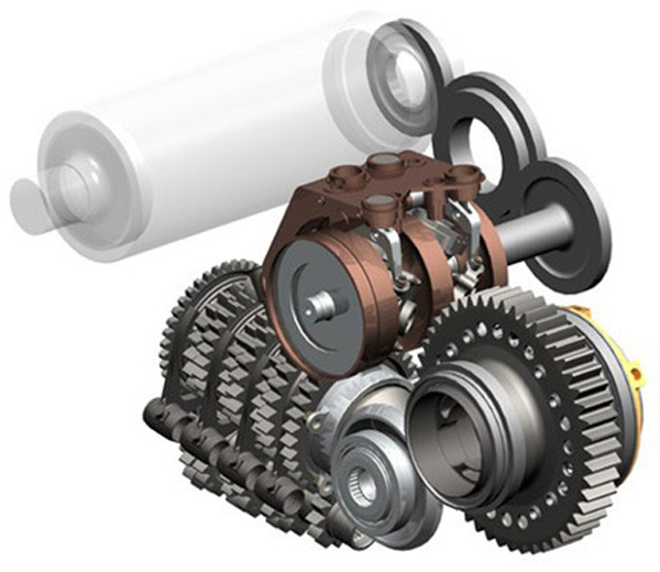
Teams have also experimented with other devices for the harvesting and application of energy. The mechanical flywheel solution (see pic above) does away with batteries. This KERS system is based on a carbon flywheel in a vacuum linked through a CVT (continuously variable transmission) to the car’s differential. The energy produced from the CVT and drivetrain under braking is used to spin the flywheel at speeds of up to 60,000-rpm, creating and maintaining rotational energy. When this energy is required, the wheels of the car are coupled to the spinning flywheel via a clutch, which when connected boosts overall power. This system is lighter, more endurable and more compact, but it doesn’t offer the same storage abilities as the battery solution.
Electro-Mechanical KERS
Williams created the electro-mechanical KERS. This system’s energy isn’t stored in batteries, but instead utilises a spinning flywheel to store the energy kinetically – what is effectively an electro-mechanical battery. Like the mechanical flywheel, it spins at a high rate, up to around 150,000-rpm to create sufficient energy. This flywheel will perform similarly to the MGU motor/generator unit of the electro-KERS system. When the flywheel spins, it creates a current in the stator, and can supply electricity, or when KERS is initiated, it can function like a motor when electricity flows from the stator. The flywheel works with the MGU, which is attached to the transmission.
Despite KERS being the most significant introductions in modern F1, it has some performance and efficiency limitations. Listed below are the 2013 technical regulations pertaining to KERS.
5.2.1 The use of any device, other than the 2.4 litre, four-stroke engine described in 5.1 above and one KERS, to power the car, is not permitted.
5.2.2 With the exception of one fully charged KERS, the total amount of recoverable energy stored on the car must not exceed 300kJ. Any which may be recovered at a rate greater than 2kW must not exceed 20kJ.
5.2.3 The maximum power, in or out, of any KERS must not exceed 60kW. Energy released from the KERS may not exceed 400kJ in any one lap. Measurements will be taken at the connection to the rear wheel drivetrain.
5.2.4 The amount of stored energy in any KERS may not be increased whilst the car is stationary during a race pit stop.
Release of power from any such system must remain under the complete control of the driver at all times the car is on the track.
The use of KERS in F1 has had an enormous impact on the car industry, as the technology has been incorporated in the manufacture of road cars. Hybrid cars are a big business now, with similar devices used to charge the batteries used to power the car when the engine isn’t required.
F1 KERS technology shifts up a gear with the new engine regulations coming into affect in 2014. As the teams fine-tune and perfect their systems, these will no doubt make the transition to creating more efficient and more economical road cars.






Speaking of kinetic…Author Kenneth Adrian Ellis has a four-part psychological power & bonus feature, revealed to readers in: A Kinetic Person's Power, Sub Titled: Voice Command Ability! 'LIKE' his Facebook Fan Page: http://www.tinyurl.com/author-kenneth-ellis.There are Press Releases, Photo/Pics, an Internet Radio Interview, and a popular You Tube Video, all @ the Fan Page! ***HIS POWER IS DOCUMENTED WITH THE LIBRARY OF CONGRESS***.